The PIC18 timer is divided into 4 types
- Timer 0
- Timer 1
- Timer 2
- Timer 3
PIC18 timers can be used to generate a time delay or as a counter to count external event happening outside the microcontroller.
In this article, we will see how to generate a time delay by programming the PIC18 timer.
Timer 0
The timer 0 module has the following features
- Software is scalable as an 8 bit or 16-bit timer/counter.
- Readable and writable
- Dedicated 8 bit software programmable Prescaler
- Clock source selectable to be internal or external
- Edge select for external clock
Register required for Timer 0
Control register
Each timer has a control register called TCON to set the various timer operation modes.
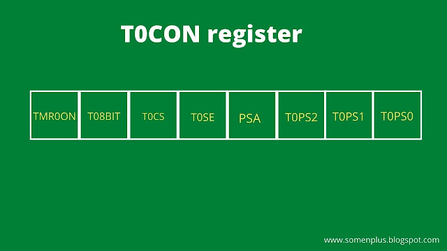
T0CON is an 8-bit register used for control of timer 0.
TOCON
TMR0ON (Timer0 on/off control bit)
1 = Enable timer 0
0 = Disable timer 0
T08BIT (Timer0 8-bit/16-bit control bit)
1 = Configured as an 8-bit timer/counter
0 = Configured as an 16-bit timer/counter
T0CS (Timer0 clock source select bit)
1 = Transition on T0CKL pin
0 = Internal instruction cycle clock (CLK0)
T0SE (Timer0 Source Edge select bit)
1 = High to Low transition on T0CKL pin
0 = Low to High transition on T0CKL pin
PSA (Timer0 Prescaler assignment bit)
1 = Timer 0 Prescaler is not assigned
0 = Timer 0 Prescaler is assigned
T0PS2 - T0PS0 (Timer0 prescaler select bit)
111 - 1:256 prescaler value
110 - 1:128 prescaler value
101 - 1:64 prescaler value
100 - 1:32 prescaler value
011 - 1:16 prescaler value
010 - 1:8 prescaler value
001 - 1:4 prescaler value
000 - 1:2 prescaler value
Load register
TMR0H (higher byte)
TMR0L (lower byte)
FLAG bit
TMR0IF (present in INTCON register)
Delay calculation for timer 0 without Prescaler value
The formula for the delay is
Delay = time period of 1 clock X max value X count
In PIC:
1 machine cycle = 4 clock
XTAL freq of PIC = 20MHz
So Frequency for I clock = 20/4 = 5MHz
Hence, time period for 1 clock = 1/5 MHz = 0.2us
Max. Value:
For 8 bit = 256
For 16 bit = 65536
Hence the modified formula for delay is
Delay = 0.2 X 10^-6 X 65536 or 256 X count
Delay calculation for timer 0 (with Prescaler)
Suppose the Prescaler ratio is 1:4 (obtained from T0PS2 - T0PS0)
So, the frequency for 1 clock = (20/4)/4 = 1.25 MHz
time period for 1clock = 1/1.25 MHz = 0.8us
Hence, the modified formula for the delay is
Delay = 0.8 X 10^-6 X 65536 or 256 X count
While calculating the count value if the value of count is less than 1 then
Delay = 0.25 X 10^-6 X count
After getting the count value
Initial count value = Max value (65536 or 256) - count
Then convert the initial count value into the HEX value and then load the MSB to TMR0H and LSB to TMR0L.
Example 1 -
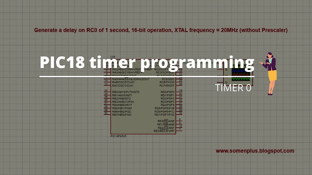
Generate a delay on RC0 of 1 second, 16-bit operation, XTAL frequency = 20MHz (without Prescaler)
Solve
1 = 0.2 X 10^-6 X 65536 X count
count = 76.26
hence count = 77
Code
#include <xc.h>
void delay_1sec(int count);
void main()
{
TRISC0=0;
while(1)
{
delay_1sec(77);
RC0=~RC0;
}
}
void delay_1sec(int count)
{
T0CON = 0x08;
unsigned int i;
for(i=0;i<count;i++)
{
TMR0H=0;
TMR0L=0;
TMR0ON=1;
while(TMR0IF==0);
TMR0ON=0;
TMR0IF=0;
}
}

