What are PIC controllers and its families?
- PIC stands for peripheral interface controller.
- It was manufactured by MICROCHIP TECH CORP in 1993.
- This controller is used in many application like audio accessories, advance medical devices, automotive industries, controlling home appliances etc.
- Some PIC families are:
- 10xxxx (10 series)
- 12xxxx (12 series)
- 14xxxx (14 series)
- 16xxxx (16 series)
- 18xxxx (18 series)
- In this article, we will see the 18 series PIC i.e. PIC18F4520.
PIC18F4520
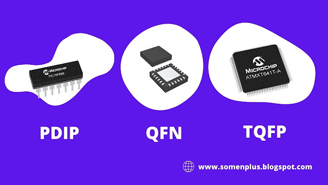
- This controller comes in three packages:
- PDIP (Plastic dual in-line package)
- QFN (quad flat no-lead package)
- TQFP (thin quad flat package)
- The first one is 40 pins (mostly used) while the other two comes with the 44-pins interface.
- This version of microcontrollers comes with CPU, timer, 10-bit ADC and other peripherals that are mainly used to develop a connection with external devices.
Features
- No. of pins 40
- CPU 8bit PIC
- Operating voltage 2 to 5.5V
- Program memory(ROM) 32K
- RAM 1536 bytes
- EEPROM 256 bytes
- ADC 10-bit
- Number of channels 13
- I/O ports A,B,C,D,E
- I/O pins 36
- Packages PDIP, QFN, TQFP
- External oscillator Up to 40MHz
- USART Protocol 1
- I2C Protocol Yes
- SPI Protocol Yes
- Brown-out reset Yes
- Watchdog timer Yes
- Comparators 2
- Master synchronous serial port(MSSP) module 1
- Capture/compare/PWM 16bit/16bit/10bit
- Power-saving sleep mode Yes
- Selectable Oscillator Option Yes
- Operating high current sink/source each pin 25mA
- Programmable high/low voltage detect Yes
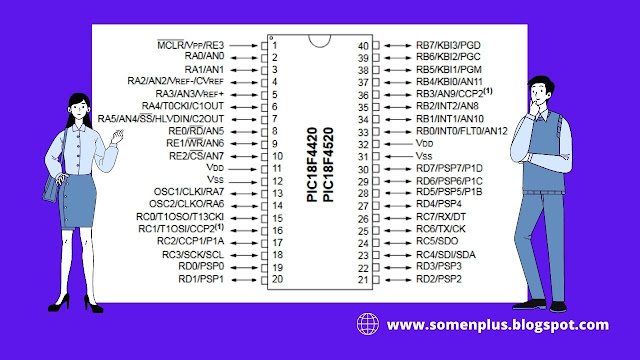
PIN Diagram of PIC18F4520
a) Digital Input/Output pins
Port A
Pin Name
2 RA0
3 RA1
4 RA2
5 RA3
6 RA4
7 RA5
14 RA6
13 RA7
Port B
Pin Name
33 RB0
34 RB1
35 RB2
36 RB3
37 RB4
38 RB5
39 RB6
40 RB7
Port C
Pin Name
15 RC0
16 RC1
17 RC2
18 RC3
23 RC4
24 RC5
25 RC6
26 RC7
Port D
Pin Name
19 RD0
20 RD1
21 RD2
22 RD3
27 RD4
28 RD5
29 RD6
30 RD7
Port E
Pin Name
8 RE0
9 RE1
10 RE2
1 RE3
b) Analog Input/Output pins
Pin Name
2 AN0
3 AN1
4 AN2
5 AN3
7 AN4
8 AN5
9 AN6
10 AN7
35 AN8
36 AN9
34 AN10
37 AN11
33 AN12
c) Parallel slave port (PSP) for digital pin
Pin Name
19 PSP0
20 PSP1
21 PSP2
22 PSP3
27 PSP4
28 PSP5
29 PSP6
30 PSP7
8 RD PSP Read control
9 WR PSP Write control
10 CS PSP Chip select control
d) Interrupt on change pin
Pin Name
37 KB10
38 KB11
39 KB12
40 KB13
e) External interrupt
Pin Name
33 INT0
34 INT1
35 INT2
f) Enhanced CCPI output
Pin Name
17 P1A
28 P1B
29 P1C
30 P1D
g) Crystal oscillator pins
Pin Name
13 OSC1 Crystal Oscillator input pin
14 OSC2 Crystal Oscillator output pin
h) Oscillator Pins for timer 1
Pin Name
15 T1OSO Oscillator output for timer1
16 T1OSI Oscillator input for timer1
i) Capture Pins
Pin Name
17 CCP1 Capture1
16 CCP2 Capture2
j) USART pins
Pin Name
25 TX Asynchronous transmit
26 RX Asynchronous receive
25 CK Synchronous clock
26 DT Synchronous data
k) ICSP programming pins
Pin Name
38 PGM ICSP programming enable pin for low voltage
39 PGC ICSP programming clock and input circuit debugger pin
40 PGD ICSP programming data and input circuit debugger pin
1 MCLR ICSP programming enable pin
l) Comparator pins
Pin Name
6 C1OUT Output comparator 1
7 C2OUT Output comparator 2
m) SPI Pins
Pin Name
23 SD1 SPI data-IN pin
24 SD0 SPI data-OUT pin
18 SCK SPI module serial clock input/output
7 SS Slave select input for SPI
n) I2C Pins
Pin Name
18 SCL I2C module synchronous serial clock input/output
23 SDA I2C data Input/Output pins
o) Other pins
Pin Name
1 Vpp Master clear active-low reset pin
32,11 Vdd Voltage pin
31,12 Vss Ground pin
4 Vref- ADC reference input voltage(low)
5 Vref+ ADC reference input voltage(high)
7 HLVDIN (high low) detect input for low voltage
33 FLTO Fault input for enhanced CCP1
15 T13CK1 External clock input for timer1/timer3
Some applications of PIC controllers
- In audio accessories
- In advance medical devices
- In the automotive industries
- Automating home appliances
- Electric door lock
- Remote sensors


