The future of AI in business and its potential to transform industries

What are the timer and its registers?

What are the timers and its registers?

banner for what is timer

  • As their name suggests, the main purpose of a timer is to measure time and count external events.
  • The 8051 microcontrollers have 2 timer/counters called T0 and T1.
  • Timers can be used for generating clock pulses used for serial communication i.e. Baudrate.

Some Timer registers are

  1. Load registers
  2. TMOD registers
  3. TCON registers

1. Load registers


explanation of load registers

  • Load registers are used to load timer counts.
  • These registers are of 16 bit.
  • The lower bit registers are called TL0/TL1.
  • The higher bit registers are called TH0/TH1.
  • TH0/TL0 is called timer 0.
  • TH1/TL1 is called timer 1.

2. TMOD (Timer mode) register

explanation of TMOD register

  • Both timer 0 and timer 1 use the same register called TMOD (Timer mode) to set the various timer operation modes.
  • TMOD is an 8-bit register.
  • The lower 4 bit for timer 0 and upper 4 bit for timer 1.
  • The upper 2 bits i.e. Gate and C/T are used to specify the operation.
  • The lower 2 bits i.e. M0 and M1 are used to set timer modes.

Different modes of timer

Mode            M1           M2            Operation

0                    0               0               13 bits
1                    0               1               16 bits
2                    1               0                8 bits
3                    1               1                split 

3. TCON ( Timer control ) register

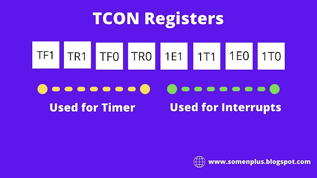
explanation of TCON register


  • The upper 4 bits are used to store the TF and TR bits of both timer 0 and timer 1.
  • The lower 4 bits are used for controlling the interrupt bits.

For Timer 1

  • TF1 = 1 (flag bit is 1 i.e. counting is completed)
  • TF1 = 0 (flag bit is zero)
  • TR1 = 1 (start counting in timer 1)
  • TR1 = 0 (stop counting in timer 1)

For Timer 0

  • TF0 = 1 (flag bit is 1 i.e. counting completed)
  • TF0 = 0 (flag bit is 0)
  • TR0 = 1 (start counting in Timer 0)
  • TR0 = 0 (stop counting in Timer 0)

Popular posts from this blog

What is machine learning and it's types?

 What is machine learning(ML)? Machine learning is a subset of artificial intelligence. Machine learning enables computers or machines to make data-driven decisions rather than being explicitly programmed for a certain task. These programs or algorithms are designed in a way that they learn and improve over time when are exposed to new data. Examples:- 1. Product recommendations   While checking for a product did you noticed when it recommends a product similar to what you are looking for? or did you noticed "the person bought this product also bought this" combination of products? How are they doing this recommendation? This is machine learning. 2. Email spam and malware filtering  There are a number of spam filtering approaches that email clients use.  To ascertain that these spam filters are continuously updated they are powered by machine learning. 3. Online customer support A number of websites nowadays offer the option to chat with customer support representati...

PIC18 Timer programming in C

The PIC18 timer is divided into 4 types Timer 0 Timer 1 Timer 2 Timer 3 PIC18 timers can be used to generate a time delay or as a counter to count external event happening outside the microcontroller. In this article, we will see how to generate a time delay by programming the PIC18 timer. Timer 0 The timer 0 module has the following features Software is scalable as an 8 bit or 16-bit timer/counter. Readable and writable Dedicated 8 bit software programmable Prescaler Clock source selectable to be internal or external Edge select for external clock Register required for Timer 0 Control register Each timer has a control register called TCON to set the various timer operation modes. T0CON is an 8-bit register used for control of timer 0. TOCON TMR0ON (Timer0 on/off control bit)                                       1 = Enable timer 0                ...

Interface relay with PIC18 microcontroller

Hi... today we will talk about another important component used in the embedded domain called a relay. Relays are electric switch which uses electromagnetism to either form or breaks the existing circuits. With the help of a relay, you can trigger a high voltage operation by a low voltage input signal. Relay is a highly versatile component that is as effective in a complex circuit as in a simple circuit. In this article, we will talk about how to interface relay with PIC18 controller. We will cover the topics in the following points: About the interfacing task Software tools used Required components Circuit diagram Code for controller Upload the HEX file Run simulation About the interfacing task In the interface relay task, with the help of a push-button, we will trigger the relay to control the lighting of the bulb which is of higher voltage. When we press the push button the microcontroller will trigger the relay to change its state, when the relay changes its state from normally clo...