Ad Code

What is USART in the PIC18 microcontroller?

 What is USART in the PIC18 microcontroller?

Before we understand what is UART first let us understand the basic communication concept and its classification 

communication classification

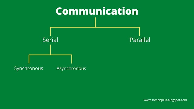
The computer transfers the data in two ways, serial and parallel.

Serial communication is effective for long-distance communication while parallel communication is effective for short-distance communication.

When a microcontroller communicates with the outside world it provides the data in bite-sized chunks.

Now the serial data communication also classified into two methods-

1. Synchronous

2. Asynchronous

The synchronous method transfers a block of data at a time, while the Asynchronous method transfers a single byte of data at a time. 

It is possible to write software to use either of these methods, but the program can be tedious and long. 

For this reason, special IC chips are made by many manufacturers for serial data communications.

These chips are commonly referred to as 

1. UART (Universal asynchronous receiver transmitter)

2. USART (universal synchronous asynchronous receiver transmitter)

The PIC18 chip has built-in USART.

Asynchronous serial communication and data framing

The data coming at the receiving end of the data line in a serial data transfer is all 0s and 1s. It is difficult to make sense of the data unless the sender and receiver agree on a set of rules, a protocol on how data is packed, how many bits constitute a character and when the data begins and ends.

Start and stop bit

Asynchronous serial data communication is widely used for character-oriented transmission. while block-oriented data transfer uses the synchronous method. 
In the asynchronous method, each character(ASCII) is placed between the start and stop bit this is called framing.

The start bit is always one bit but the stop bit can be 1 or 2 bit. The start bit is always low(0) and the stop bit always high(1).

bit image

Serial port connection

RS232

To allow compatibility among data communication equipment made by various manufacturers and interfacing standard RS232 was set by the electronics industries association(EIA).
In RS232 a 1 is represented by -3V to -25V while a 0 bit is +3V to +25V making -3V to +3V undefined.
To connect any RS232 to a microcontroller system we must use a voltage converter such as MAX232 voltage level.

Tx and Rx pin of PIC18

The PIC18 has 2 pins that are used specifically for transferring and receiving data serially. These two pins are Tx and Rx (RC6 and RC7).
These pins are TTL compatible therefore they require a line driver to make them RS232 compatible.

MAX232

Because the RS232 is not compatible with today's microprocessor and microcontrollers we need a line driver to convert the RS232 signals to a TTL voltage level that will be acceptable to the PIC18 Tx and Rx pins.

USART

The USART in the PIC18 has both synchronous and asynchronous features. The synchronous mode can be used to transfer data between the PIC and the external peripheral such as ADC and EEPROM.

The asynchronous mode is the one we will use to connect the PIC18 based system to the serial port for the purpose of full-duplex serial data transfer.

Registers of USART

In the PIC18 microcontroller, 6-major registers are associated with the UART
  1. SPBRG
  2. TXREG
  3. RCREG
  4. TXSTA
  5. RCSTA
  6. PIR1

SPBRG register

The PIC18 transfers and receives data serially at many different baud rates.
Some PC baud rates are 11200, 2400, 4800, 9600, 19200, 38400, 57600, 115200.

The baud rate in the PIC is programmable this is done with the help of the 8-bit register called SPBRG.
For a given crystal frequency the value loaded into the SPBRG decides the baud rate.

The relation between the value loaded into the SPBRG and the Fosc is dictated by the following formula:-

desired baud rate = Fosc / 64(X + 1)

X = value we load into SPBRG

Example:- 

Assuming, Fosc = 20MHz
desired baud rate = 20 x 10^6/64(X + 1) = 312500/(X + 1)

X = (312500/desired baud rate) - 1

if baud rate = 9600

then, X = (312500/9600) - 1 = 31.552 = 32

hence,  SPBRG = 32 

TXREG register

TXREG is another 8-bit register used for serial communication in the PIC18. For a byte of data to be transferred via the Tx pin, it must be placed in the TXREG register.

TXREG is a special function register and can be accessed like any other register in the PIC18

RCREG register

When the bits are received serially via the Rx pin the PIC18 defames them by eliminating the stop and start bit making a byte out of the data received and then placing it in the RCREG register.

TXSTA(Transmit status and control register)

It is an 8-bit register, it is used to select synchronous/asynchronous modes and data framing size.
The BRGH bit is used to select a higher speed for transmission.

TXSTA register diagram

CSRC - clock source select bit
              0 = asynchroneous
              1 = synchroneous

TX9 - 9-bit transmit enable
              0 = select 8-bit transmission
              1 = select 9-bit transmission

TXEN - Transmit enable
              0 = transmit disable
              1 = transmit enable

SYNC - USART mode select
              0 = asynchroneous
              1 = synchroneous

BRGH - High baud rate select
              1 = high speed
              0 = low speed 

TRMT - Transmit shift register status 
              1 = TSR empty
              0 = TSR full

TXD9 - 9th bit of transmitting data
              Because we use the 8-bit option we make TXD9 = 0, can be used as an address/data or a parity bit in some application.

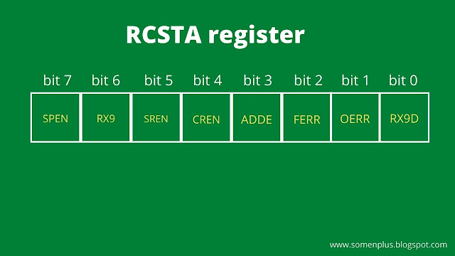
RCSTA (receive status and control register)

It is an 8-bit register. It is used to enable the serial port to receive data

RCSTA register diagram

SPEN - serial port enable bit
              0 = serial port disable
              1 = serial port enable

RX9 - 9-bit receive enable
              0 = select 8-bit reception
              1 = select 9-bit reception

SREN - Single receive enable
              0 = asynchroneous
              1 = synchroneous

CREN - Contineous receive enable bit
              0 = disable continuous receive (asynchroneous)
              1 = enable continuous receive (asynchroneous)

ADDEN - Address delete enable bit
              because used with 9-bit data frame ADDEN=0

FERR - Framing error bit 
              1 = framing error
              0 = no framing error

OERR - Over run error 
              1 = over run error
              0 = no over run error

RXD9 - 9th bit of transmitting data
              Because we use the 8-bit option we make RXD9 = 0, can be used as an address/data or a parity bit in some application.

PIR1(Peripheral interrupt request register 1) register

PIR1 register diagram

RCIF - Receive interrupt flag bit 
              1 = The UART has received a byte of data and it is sitting in the RCREG register waiting to be picked up
              0 = RCREG is empty

TXIF - Transmit interrupt flag bit 
              1 = TXREG register is empty
              0 = TXREG register is full

Step for programming the PIC18 to transfer data serially 

  1. The TXSTA register is loaded with the value 20H indicating asynchronous mode with an 8-bit data frame, low baud rate and transmit enabled.
  2. Make TX pin of PORTC (RC6) output for data to come out of the PIC.
  3. The SPBRG is loaded with one of the value.
  4. SPEN bit in the RCSTA register is set HIGH to enable the serial port of the PIC18.
  5. The character byte to be transmitted serially is written into the TXREG register.
  6. Monitor the TXIF bit of the PIR1 register to make sure UART ready for the next byte.
  7. To transfer the next byte go to step5.

Steps for programming the PIC18 to receive data serially

  1. The RCSTA register is loaded with the value 90H to enable the continuous receive in addition to the 8-bit data size option.
  2. The TXSTA register is loaded with the value of  00H to choose the low baud rate option.
  3. SPBRG is loaded.
  4. Make the RX pin of PORTC an input for data to come into the PIC18.
  5. The RCIF flag bit of the PIR1 register is monitored for a high to see if an entire character has been received yet.
  6. When RCIF is raised the RCREG register has the byte. its contents are moved into a safe place.
  7. To receive the next character go to step5.