Interfacing 4x3 Keypad with PIC18F4520 controller

The keypad is one of the most widely used peripheral devices, from our academics projects to industrial use whenever user interface is required we remember the keypad for our embedded systems. Hence learning how to interface keypad to different-different controllers becomes important.
In this article, we will see how to interface a 4x3 keypad to the PIC18F4520 controller.
We will cover the topics on the following points:-
- About the project
- Selecting the required components
- Circuit diagram
- Writing the code for the controller
- Uploading the HEX file to the controller
- Simulating the project
About the project
In this project, the keypad is connected to Port B and the data pins are connected to the Port D of the PIC controller. Data controlling pin of the LCD are connected to pin 3.0, pin 3.1, pin 3.2 of port C.
In this simple project initially, the LCD display will print the name of this blog page "Code somenplus" and then it will ask to enter the digits from the keypad. Whatever digit you will press it will display on the LCD screen.
Software tools
- Proteus professional 8 (project simulation)
- MP Lab IDE (writing code for the controller)
Selecting the required components
For the completion of this project simulation, the components that required are:
- PIC18F420 controller
- LM016L 16x2 LCD display
- 4x3 Phone keypad
Circuit diagram

Please make sure all the pins are connected properly.
Writing the code for the controller
The code for the controller is given below
#include <xc.h>
#define _XTAL_FREQ 20000000
#define rs RC0
#define rw RC1
#define en RC2
#define col0 RB0
#define col1 RB1
#define col2 RB2
#define row0 RB4
#define row1 RB5
#define row2 RB6
#define row3 RB7
void lcd_data(unsigned char data);
void lcd_cmd(unsigned char command);
void lcd_string(const unsigned char *string, unsigned char length);
void lcd_initialize();
void keypad();
void main()
{
TRISD=0;
TRISC=0;
TRISB=0xF0;
lcd_initialize();
lcd_cmd(0x80);
lcd_string("Code Somenplus",14);
__delay_ms(2000);
lcd_cmd(0x01);
lcd_cmd(0x80);
lcd_string("Enter Digits",12);
lcd_cmd(0xc0);
while(1)
{
keypad();
}
}
void lcd_data(unsigned char data)
{
PORTD=data;
rs=1;
rw=0;
en=1;
__delay_ms(5);
en=0;
}
void lcd_cmd(unsigned char command)
{
PORTD=command;
rs=0;
rw=0;
en=1;
__delay_ms(5);
en=0;
}
void lcd_string(const unsigned char *string, unsigned char length)
{
unsigned char i;
for(i=0;i<length;i++)
{
lcd_data(string[i]);
}
}
void lcd_initialize()
{
lcd_cmd(0x38);
lcd_cmd(0x06);
lcd_cmd(0x0c);
lcd_cmd(0x01);
}
void keypad()
{
col0=1;
col1=0;
col2=0;
if(row0==1)
{
lcd_data('1');
while(row0==1);
}
if(row1==1)
{
lcd_data('4');
while(row1==1);
}
if(row2==1)
{
lcd_data('7');
while(row2==1);
}
if(row3==1)
{
lcd_data('*');
while(row3==1);
}
col0=0;
col1=1;
col2=0;
if(row0==1)
{
lcd_data('2');
while(row0==1);
}
if(row1==1)
{
lcd_data('5');
while(row1==1);
}
if(row2==1)
{
lcd_data('8');
while(row2==1);
}
if(row3==1)
{
lcd_data('0');
while(row3==1);
}
col0=0;
col1=0;
col2=1;
if(row0==1)
{
lcd_data('3');
while(row0==1);
}
if(row1==1)
{
lcd_data('6');
while(row1==1);
}
if(row2==1)
{
lcd_data('9');
while(row2==1);
}
if(row3==1)
{
lcd_data('#');
while(row3==1);
}
}
After writing the code on MP lab IDE all you need to compile the code and build a hex file for the controller.
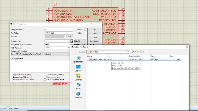
Uploading the HEX file to the controller
For uploading the HEX file all you need to double click on the controller and select the HEX file you created.

After uploading the HEX file don't forget to change the clock frequency from 4MHz to 20MHz.
Simulate the project
Video